
Mimic Backlash Stiction Block
By Gregory McMillan
Summary
All control valves have backlash and stiction. Backlash shows up as deadband and stiction (friction) shows up as a resolution limit. Upon a signal reversal, the signal must exceed the deadband before the valve starts to move. There is lost motion equal to the deadband. Backlash originates in a slight play in linkage and connections between the actuator, shaft, stem and internal closure member (e.g., plug, disk, or ball), more commonly known as “trim”. Deadband can also originate from a setting in the control system. Variable Frequency Drives (VFD) often have an excessive deadband setting to reduce the response to noise not realizing the detrimental effect on process control. Deadband will result in a limit cycle if there are two or more integrators in the process and control system including the positioner. The amplitude and period of the limit cycle can be reduced by increasing the PID gain.
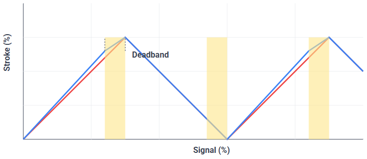
Figure 1. Backlash and Deadband. Shows lost motion upon signal reversal.
For a signal change in the same direction, the change must exceed the resolution before the valve starts to move at which point the valve position theoretically steps by the resolution amount. The result is a stair case response with equal steps in position. Resolution limits can also originate from the teeth of a rack and pinion actuator or shaft windup in a rotary valve where the shaft twists, but the trim does not move due to high seal friction.
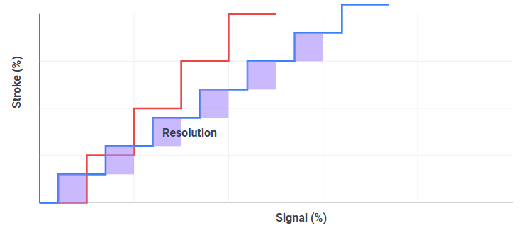
Figure 2. Stiction and Resolution. Shows staircase response due to stick-slip.
For a threshold sensitivity limit, the valve position will match the signal once it exceeds the sensitivity. Actuators and positioners have more of a sensitivity limit than a resolution limit and in some cases stiction may show up more like a threshold sensitivity limit. There is very little distinction in the literature between resolution and sensitivity. The fact that both cause a limit cycle if there are one or more integrators in the process or control system including the positioner diminishes the need to distinguish between them. The difference may show up with external-reset feedback in terms of the position being closer to the signal from a sensitivity limit when all integral action is suspended. The amplitude of the limit cycle is proportional to the product of the resolution or threshold sensitivity and open loop gain. The period of the limit cycle can be reduced by increasing the PID gain.
The ISA Standard ISA-75.25.01 and Technical Report ISA-TR75.25.02 on Valve Response testing cites the need to find the deadband (DBv) and resolution (Rv) and 86% response time T86.
The best most responsive control valves, such as the Fisher Baumann, have a deadband of about 0.2% and resolution of 0.1% and a T86 time of 1 sec for small step changes. These values can be used if you want to see the best case scenario. Digitally actuated valves may have an even better response but such valves are not commonly used. An on-off rotary valve posing as a throttling valve has been observed to have a deadband of 10% and resolution of 8% or more. Furthermore, the readback from a smart positioner of actuator shaft thinks the valve is moving when the internal trim is not. On-off valves are commonly used for throttling because they have a tighter shutoff, a lower price than a true throttling valve, the poor response is not seen in diagnostics since the positioner is lying to them and the consequences are not understood. Since valve specification forms have leakage but not for deadband, resolution or response time, the problem is epidemic except for refineries who realized the problem in the implementation of Model Predictive Control (MPC). Control valve suppliers have become more resistant to the idea of having to meet values put on a specification form especially since the resolution and response time specifications are difficult to meet near the seat (e.g., positions less than 10%) and for small signal changes (e.g., steps less than 0.25%). Furthermore, piston actuators have a threshold sensitivity of 1% or more and many positioners have a T86 time that increases to 40 sec and 80 sec for changes less than 0.25% in the same and reverse direction, respectively. Normally responsive positioners may be terrible when modified to reduce air consumption.
Once the signal gets beyond the resolution or deadband, the response is delayed by a pre-stroke deadtime that for small valves is less than a second but can be as large as 10 sec for extremely big valves that have no volume booster on the positioner output. There is then a second order exponential response corresponding to a small and large time constants (lags) in series. The resulting response is rate (velocity) limited for large valves based on the slewing rate (%/sec) or stroking time (sec for 100% stroke) estimated by valve supplier or found by testing. The T86 response time corresponds to the deadtime plus twice the sum of the two lags plus the effect of rate limiting. For pressure and surge control, rate limiting and T86 is an issue because the valves are large and T86 must be less than 2 seconds for large step changes. For much more on the importance of getting the valve response right is in the March 2016 Control feature article “How to specify valves and positioners that don’t compromise control”.
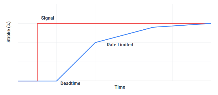
Figure 3. Valve Response with Deadtime, Rate Limiting, and Exponential Lags.
The blocks can be put in series to simulate the actuator-shaft and stem-trim to show poor readback from a positioner being lied to by an on-off valve posing as a throttling valve.
Inputs
SIGNAL - controller signal to actuator (0-100%)
SOLENOID_VALVE - discrete input causing valve to freeze at last position
ON_OFF_DISCRETE - discrete input causing valve to go closed or wide open
FOLLOW - discrete that bypasses lags in exponential response when energized
Outputs
STROKE - current position of actuator (%)
Top 10 things you don’t want to hear during a new plant startup
As originally seen in “Control Talk: Modeling and control opportunities”, Control Talk column by Greg McMillan
Controllers all have tuning settings with gain and reset in repeats per minute equal to one.
We used tieback simulations with the gain and time constant equal to one.
Advanced operator graphics eliminated the need for an OTS.
All alarms available were used and set based on vintage process flow diagrams.
All analyzers are in an analyzer house.
All transmitters are at ground level.
We use tight shutoff rotary valves, so we have the greatest capacity and least leakage.
The mechanical engineers will ensure the equipment and piping work well.
The vintage process and instrument diagrams told us everything we needed.
We just did a copy of another plant’s configuration and interface.
Useful Resources

For additional information on this and other various control topics, check out the Control Talk Column and PlantWise Industrial Consulting Blog.
Version History
Sep 22, 2018 (Original Post)